The Altec 1591A is a somewhat legendary device; a crunchy, solid-state limiter that has a ridiculously high gain mic preamp as well as a line level input. Of course, it also has an Altec Green faceplate – clearly the sign of vintage!
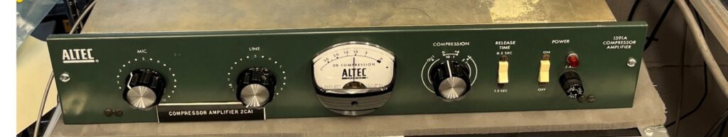
Seriously, people love the sound of these devices. Cruising the web you see things like “crunchy midrange thing going on”, “a unique sound”, “definitely a character piece”.
What’s the secret to the sound?
The secret to the 1591A’s sound is a combination of things. Start with the Altec 1588 mic preamp module. This is a high gain, plug in pre-amp common to devices of this age. Then feed the signal to another reasonably high gain discrete stage and put a light dependent resistor (photocell) across the signal path to introduce limiting.
Finish with a push pull output stage feeding a medium grade line output transformer and this thing is full of delightful harmonics that only get better when you limit harder.
Photocell resistors fed by actual light bulbs are totally 60’s. The lamp/photocell combo is slow to react, so there’s some overshoot, and when the value does change it’s smooth and sounds great.
Why do they die?
Lots of things change as electronic equipment ages. Electrolytic capacitors lose their value, cutting off low frequencies and even changing the gain structure. These are easily replaced.
In the case of the Altec 1591A, a couple of items are unobtainable in 2023; the output transformer and the photocell. Most frequently, the photocells die. You are left with a high gain pre-amp, with no limiting.
Bringing it back to life
The photocells used in the 1591A were made by GE in the 1950’s and 1960’s. There’s no information about the lamp component or the photo-resistor side. Modern photocell type devices use LEDs, and the turn on characteristics of LEDs are completely different than an incandescent lamp. You may have seen what happens when you use an LED lamp with a home dimmer. Nothing, nothing, nothing, bright! LED photocells are not an option.
With no information on specifications, I dug in and started experimenting. First, I had to make something that held the lamp and photoresistor close together and kept external light out. 3D printing to the rescue!
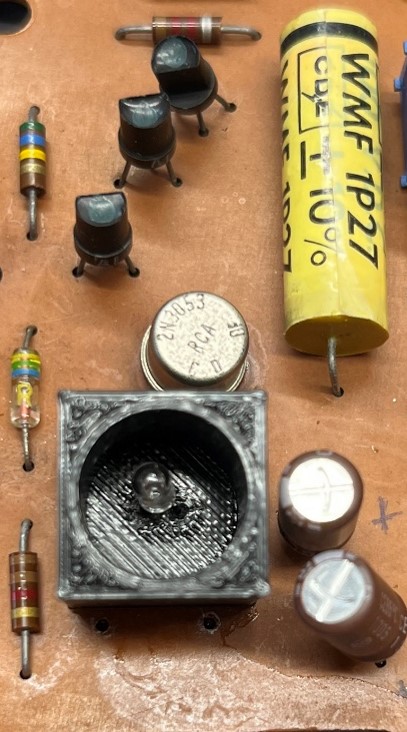
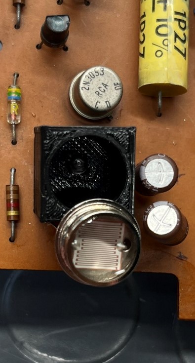
3D printed enclosure with the photoresistor added but not fully in place
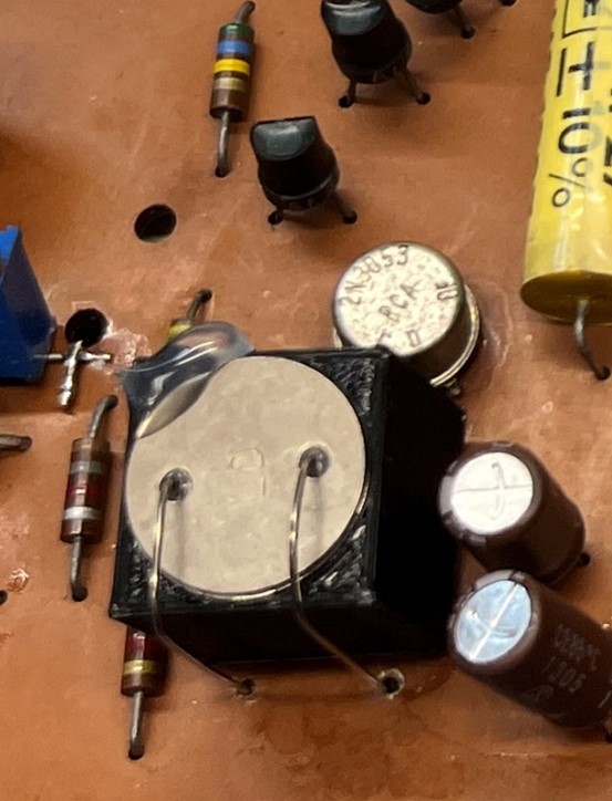
Final assembly with photoresistor glued in place
Matching the old sound
Here was the challenge. How to make this 60-year-old device come back to life without breaking its signature sound? I spent a lot of time reviewing how the lamp was driven, understanding the subtle impact of the side-chain driving the lamp. The photo-resistor was a bit easier, it just had to be a very low impedance device when illuminated. But getting the gain reduction curves in line was challenging.
Fortunately, Altec provides great information in their manuals of the time. The chart below shows output level on the vertical and input level on the horizontal axis.
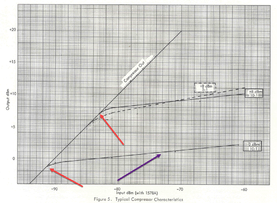
The red arrows point to the first critical element, the inflection point of limiting at the 0dB and +8dB settings. The violet arrow points to the other key; the ratio of limiting. Since this was primarily designed for microphone limiting, the input level is shown as mic level increasing from nearly nothing, through -90dBM input to -60dBM with the output from -4dBm to +20dBm. The key is how the output (vertical) lines curve away from the straight line as level increases.
I generally test limiters at line level, the graph below shows a -40dBU signal in rising to +20dBU output with the compressor out, 0dB-10:1, +8dB-10:1 and +8dB-5:1 ratio. BTW, I use dBU in my testing, in which the reference for 0 = 775mV but does not require a 600 Ohm load like the dBm reference in the Altec literature. For our purposes, 0dBU = 0dBM as I have loaded the output of the 1591A with 600 Ohms.
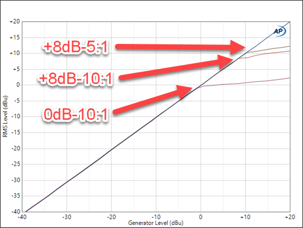
Note that the bottom two curves almost identically match the transition and ratio. I was not able to match the +8dB-5:1, unfortunately.
I ran a complete series of tests on the unit including FFT analysis at multiple frequencies without limiting, with 2dB of limiting and 8dB of limiting. These are linked at the end of this posting.
Mic Gain
As noted above, these devices shipped with 90dB of gain, an unbelievable amount of gain; especially for modern microphones. Fortunately, the mic preamp module can have its gain lowered, so I added a switch in the rear to switch from 90dB of gain to ~70dB of gain to enable smoother use of modern mics. It is much more useful at 70dB of gain! The 1591A also allowed line input, via a bridging input transformer module.
Altec 1591A Repairs
If you have an Altec 1591A that is not functioning properly, please contact me at http://www.ms-tas.com/contact.
Full Report on Altec 1591A after Repairs
I use an Audio Precision 515 and run comprehensive reports after every repair. Here is a link to the Comp/Limit report, here is a link to the 90dB gain Mic Preamp and here is a link to the 70dB gain Mic Preamp.